How an ALU Works: Build a 1-Bit Arithmetic Logic Unit
Learn how an ALU works inside a CPU using logic gates, adders, two's-complement subtraction, multiplexers, control signals, and status flags.

In the previous chapter, we built half-adders, full-adders, an 8-bit ripple-carry adder, and simple memory circuits. Those components introduced the two abilities every processor needs: transforming binary values and preserving state.
The next step is to combine arithmetic and logical circuits into an Arithmetic Logic Unit, usually abbreviated to ALU. The ALU is the part of a processor that performs operations such as addition, subtraction, AND, OR, XOR, comparisons, and sometimes shifts.
This chapter explains how an ALU works from the inside out. We will begin with subtraction and two’s complement, examine logical operations and status flags, learn how multiplexers select an operation, and finally build a simple 1-bit ALU that can be expanded into an 8-bit, 16-bit, or 32-bit design.
What You Will Learn
By the end of this chapter, you will understand:
- what an arithmetic logic unit does inside a CPU;
- how an ALU differs from the control unit;
- how half-subtractors and full-subtractors work;
- why practical ALUs usually reuse an adder for subtraction;
- how two’s-complement subtraction works;
- how logic operations are performed bit by bit;
- how multiplexers select the required result;
- the difference between an instruction opcode and an ALU control signal;
- why a 1-bit ALU needs carry-in and carry-out;
- how one-bit ALU slices form a multi-bit ALU;
- what the zero, carry, negative, and overflow flags mean.
What Is an ALU?
An Arithmetic Logic Unit is a digital circuit that performs operations on binary values.
The ALU normally receives one or more operands from CPU registers. It also receives control signals that specify which operation to perform. After processing the operands, it produces:
- a result;
- status information about that result.
A simplified ALU might support:
- addition;
- subtraction;
- bitwise AND;
- bitwise OR;
- bitwise XOR;
- bitwise NOT;
- equality or ordering comparisons;
- left and right shifts.
Different processor designs support different operation sets. Multiplication, division, floating-point arithmetic, and complex shifts may be handled by the main ALU, by specialized execution units, or by multi-cycle circuits elsewhere in the processor.
The ALU should therefore be understood as an execution circuit, not necessarily one single universal block that performs every mathematical operation in a modern CPU.
Where the ALU Fits Inside a CPU
The ALU does not work alone. It forms part of a larger data path that includes:
- registers;
- multiplexers;
- buses;
- the control unit;
- instruction-decoding logic;
- memory interfaces;
- status registers.
A typical operation follows this simplified sequence:
- The control unit decodes an instruction.
- Source values are read from registers.
- Control signals configure the ALU.
- The ALU performs the selected operation.
- The result is written to a destination register or used to calculate an address.
- Status flags may be updated.
For example, an instruction that adds two registers might conceptually perform:
R3 = R1 + R2The register file supplies the values stored in R1 and R2. The ALU adds them, and the result is written into R3.
ALU vs Control Unit
The ALU performs data operations.
The control unit coordinates the processor and decides which actions happen during an instruction.
A useful distinction is:
- the ALU answers: What result do these inputs produce under this operation?
- the control unit answers: Which values should be used, which operation should run, and where should the result go?
The ALU does not independently read a program instruction and decide what to do. Instruction-decoding logic translates the instruction into lower-level control signals for the data path.
Arithmetic Operations Inside an ALU
Addition is the foundation of many arithmetic operations.
With an adder and some additional control logic, a processor can implement:
- addition;
- subtraction;
- increment;
- decrement;
- comparisons;
- address calculations.
Before examining the efficient adder-subtractor design used in many ALUs, it is helpful to understand binary subtraction directly.
Binary Subtraction Basics
Binary subtraction follows rules similar to decimal subtraction.
The four possible one-bit cases are:
0 - 0 = 0
1 - 0 = 1
1 - 1 = 0
0 - 1 = 1 with a borrow
The final case cannot be represented using one unsigned bit without borrowing from the next higher position.
This produces two outputs:
- Difference, the result bit;
- Borrow, an indication that the next stage must supply one unit.
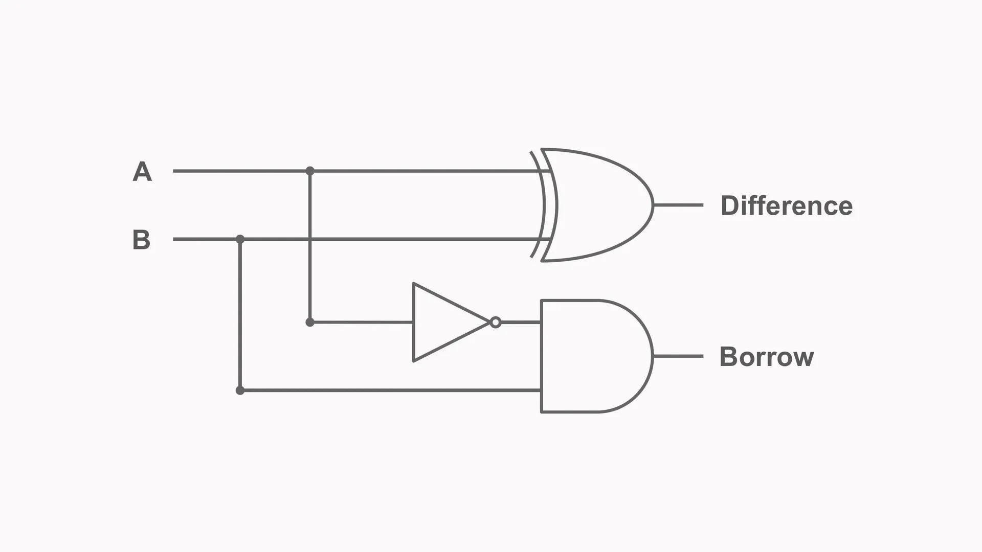
Building a Half-Subtractor
A half-subtractor subtracts one input bit B from another input bit A.
It produces:
Difference;Borrow.
The truth table is:
A | B | Difference | Borrow |
|---|---|---|---|
| 0 | 0 | 0 | 0 |
| 0 | 1 | 1 | 1 |
| 1 | 0 | 1 | 0 |
| 1 | 1 | 0 | 0 |
The Difference output follows XOR:
Difference = A XOR BThe Borrow output is high only when A is 0 and B is 1:
Borrow = (NOT A) AND BThis requires:
- one XOR gate;
- one NOT gate;
- one AND gate.
The half-subtractor works for one binary column, but it cannot include a borrow from a less significant position.
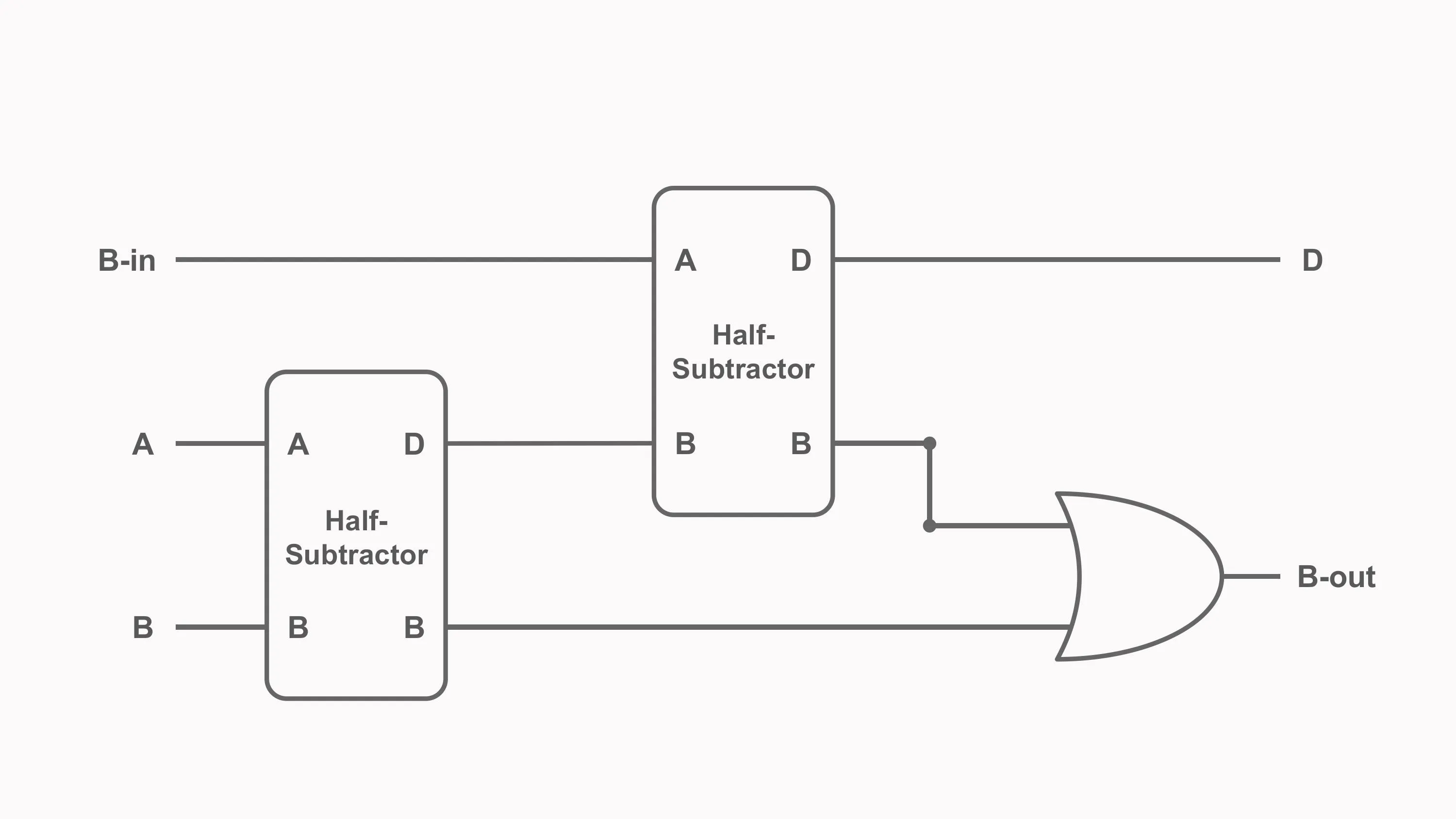
Building a Full-Subtractor
A full-subtractor subtracts two bits while also accepting a borrow-in value.
Its inputs are:
A;B;- borrow-in
B_in.
Its outputs are:
Difference;- borrow-out
B_out.
The full-subtractor truth table is:
A | B | B_in | Difference | B_out |
|---|---|---|---|---|
| 0 | 0 | 0 | 0 | 0 |
| 0 | 0 | 1 | 1 | 1 |
| 0 | 1 | 0 | 1 | 1 |
| 0 | 1 | 1 | 0 | 1 |
| 1 | 0 | 0 | 1 | 0 |
| 1 | 0 | 1 | 0 | 0 |
| 1 | 1 | 0 | 0 | 0 |
| 1 | 1 | 1 | 1 | 1 |
The Difference output is:
Difference = A XOR B XOR B_inOne valid expression for borrow-out is:
B_out = ((NOT A) AND B) OR (B_in AND (NOT (A XOR B)))A full-subtractor can be built from:
- two half-subtractors;
- one OR gate.
The construction works as follows:
- The first half-subtractor calculates
A - B. - The second subtracts
B_infrom the first Difference. - The OR gate combines the two possible borrow outputs.
Multiple full-subtractors can be chained to subtract wider binary values. The borrow signal then travels from one stage to the next.
Why Real ALUs Usually Reuse the Adder
A dedicated subtractor is useful for learning, but many practical ALUs do not contain a completely separate multi-bit subtractor.
Instead, they perform subtraction with the existing adder by using two’s complement.
The key identity is:
A - B = A + (NOT B) + 1To subtract B from A, the circuit:
- inverts every bit of
B; - sets the initial carry-in to
1; - sends the values through the normal adder.
This means the same chain of full-adders can perform both addition and subtraction.
Two’s-Complement Subtraction
Consider the four-bit calculation:
0101 - 0011These values are decimal 5 and 3.
First, invert every bit of B:
B       = 0011
NOT B   = 1100
Then add 1:
1100 + 1 = 1101Now add the two’s complement of B to A:
  0101
+ 1101
------
1 0010
With a fixed four-bit result, the carry beyond the most significant bit is discarded:
0010Binary 0010 is decimal 2, so the result is correct.
Building an Adder-Subtractor Circuit
A simple adder-subtractor can use one control signal called SUB.
For each bit of B, an XOR gate combines B with SUB:
B_selected = B XOR SUBThe same SUB signal also becomes the initial carry-in.
Addition Mode
When:
SUB = 0then:
B XOR 0 = B
carry-in = 0
The circuit calculates:
A + BSubtraction Mode
When:
SUB = 1then:
B XOR 1 = NOT B
carry-in = 1
The circuit calculates:
A + (NOT B) + 1which is equivalent to:
A - BThis is an important example of hardware reuse: a small amount of control logic allows one adder to perform two operations.
Incrementing and Decrementing
An incrementer adds one:
A + 1A decrementer subtracts one:
A - 1These operations can also reuse the ALU’s adder-subtractor circuit.
For increment:
B = 00000001
operation = ADD
For decrement:
B = 00000001
operation = SUBTRACT
A processor may also include specialized increment logic in places where a value must advance frequently, such as a program counter. The exact implementation depends on the architecture and timing requirements.
Logic Operations Inside an ALU
The logic portion of an ALU performs bitwise operations.
A bitwise operation applies the same Boolean function independently to each pair of corresponding bits.
Consider:
A = 1010
B = 1100
Bitwise AND
Each output bit is 1 only when both input bits are 1:
  1010
AND
  1100
------
  1000
Bitwise OR
Each output bit is 1 when at least one input bit is 1:
  1010
OR
  1100
------
  1110
Bitwise XOR
Each output bit is 1 when the two input bits are different:
  1010
XOR
  1100
------
  0110
Bitwise NOT
NOT inverts every bit of one operand:
NOT 1010 = 0101These operations are widely used for:
- masking bits;
- setting or clearing flags;
- testing individual fields;
- combining packed values;
- implementing low-level algorithms;
- controlling hardware registers.
Logic Operations and Program Decisions
Logic operations alone do not make a program branch. Instead, the ALU produces results and status information that other processor circuits can use.
For example, a processor can compare two values by subtracting them:
A - BThe numerical result and status flags reveal relationships between the operands.
Examples include:
- a zero result can indicate equality;
- a negative signed result may help determine signed ordering;
- carry or borrow information can help determine unsigned ordering;
- overflow affects how a signed result must be interpreted.
The control unit then uses instruction rules and these status conditions to decide whether a branch should occur.
Comparisons Without a Dedicated Comparator
Some ALUs include dedicated comparison circuitry, but comparisons can also reuse subtraction.
To test:
A == Bthe ALU calculates:
A - BIf the result is zero, the operands are equal.
To compare signed or unsigned values, the processor must interpret several status signals correctly. A simple negative result is not sufficient for every signed comparison because signed overflow can make the sign bit misleading.
This is why processors track multiple flags rather than only the raw result.
ALU Status Flags
An ALU often produces status signals alongside its main result.
Common flags include:
- Zero flag (
Z) - Carry flag (
C) - Negative or sign flag (
N) - Overflow flag (
VorO)
Architectures use different names and may include additional flags.
Zero Flag
The zero flag is set when every result bit is zero:
Result = 00000000A wide NOR-style reduction can test whether any bit is 1. If none are high, the zero flag becomes active.
The zero flag is commonly used for equality tests and loop conditions.
Carry Flag
For addition, the carry flag often reflects the carry out of the most significant bit.
In unsigned arithmetic, this indicates that the mathematical result did not fit within the available width.
For example, with four-bit values:
1111 + 0001 = 1 0000The stored four-bit result is 0000, and the carry-out is 1.
Subtraction conventions vary between architectures. Some processors treat the carry flag as no borrow, while others expose borrowing differently. The instruction-set definition determines the exact meaning.
Negative Flag
The negative flag commonly copies the most significant bit of the result.
In two’s-complement representation, the most significant bit acts as the sign bit:
0normally indicates a non-negative result;1normally indicates a negative result.
This flag is useful, but it must be considered together with overflow when interpreting signed comparisons.
Overflow Flag
Signed overflow occurs when the true signed result cannot be represented in the available number of bits.
For addition, overflow occurs when:
- two positive operands produce a negative-looking result;
- two negative operands produce a positive-looking result.
For example, in four-bit two’s complement:
0111 = 7
0001 = 1
Adding them gives:
0111 + 0001 = 1000Four-bit 1000 represents -8, not 8. The result width is too small, so signed overflow occurred.
Carry and overflow are different:
- carry is primarily relevant to unsigned arithmetic;
- overflow is relevant to signed arithmetic.
A result can produce carry without signed overflow, signed overflow without carry, both, or neither.
What Are ALU Control Signals?
The ALU needs control inputs that select an operation.
A simple teaching ALU might use a two-bit signal:
| Control | Operation |
|---|---|
00 | AND |
01 | OR |
10 | XOR |
11 | ADD |
A more capable ALU needs more control combinations. For example:
| ALU control | Operation |
|---|---|
000 | ADD |
001 | SUBTRACT |
010 | AND |
011 | OR |
100 | XOR |
101 | SHIFT LEFT |
110 | SHIFT RIGHT |
111 | COMPARE |
This mapping is a design choice, not a universal standard.
Opcode vs ALU Control Signal
An instruction opcode identifies an operation in the processor’s instruction set.
An ALU control signal configures the hardware inside the data path.
These are related, but they are not always identical.
An instruction decoder may examine:
- the main opcode;
- function fields;
- instruction format;
- addressing mode;
- current processor state.
It then generates several internal control signals, including the code sent to the ALU.
One instruction can therefore control much more than the ALU. It may also determine:
- which registers are read;
- which register receives the result;
- whether memory is accessed;
- whether an immediate value is selected;
- whether the program counter changes;
- whether status flags are updated.
Saying that the opcode goes directly into the ALU is a useful first approximation, but real processors normally contain a decoding stage between the instruction and the ALU controls.
What Is a Multiplexer?
A multiplexer, or MUX, selects one input from several possible inputs and forwards it to one output.
A two-bit select signal can choose one of four inputs:
| Select | Chosen input |
|---|---|
00 | Input 0 |
01 | Input 1 |
10 | Input 2 |
11 | Input 3 |
Inside a simple ALU, separate circuits may produce:
- an AND result;
- an OR result;
- an XOR result;
- an arithmetic result.
A multiplexer uses the ALU control signal to choose which result appears at the output.
Are All ALU Operations Calculated in Parallel?
In a simple educational design, the operation circuits can receive the same operands simultaneously, and a multiplexer selects one result.
This makes the design easy to understand, but real implementations can be more complicated.
A processor designer may:
- share hardware between operations;
- disable unused circuits to save power;
- divide operations across separate execution units;
- perform complex operations over multiple cycles;
- pipeline an operation into several stages.
The parallel-circuit model is therefore a valid way to learn selection logic, but it should not be treated as the only possible ALU architecture.
Building a Simple 1-Bit ALU
A 1-bit ALU slice processes one bit from each operand.
To support arithmetic correctly, the slice needs more than only A, B, and one output.
A useful design has:
Inputs
AB- carry-in
C_in - operation control
Outputs
- result bit
Y - carry-out
C_out
For simplicity, our ALU supports four operations:
| Control | Operation | Output |
|---|---|---|
00 | AND | A AND B |
01 | OR | A OR B |
10 | XOR | A XOR B |
11 | ADD | A + B + C_in |
The AND, OR, and XOR circuits each produce one candidate output. A full-adder produces:
- an arithmetic Sum;
- a carry-out.
A four-to-one multiplexer selects the final result bit.
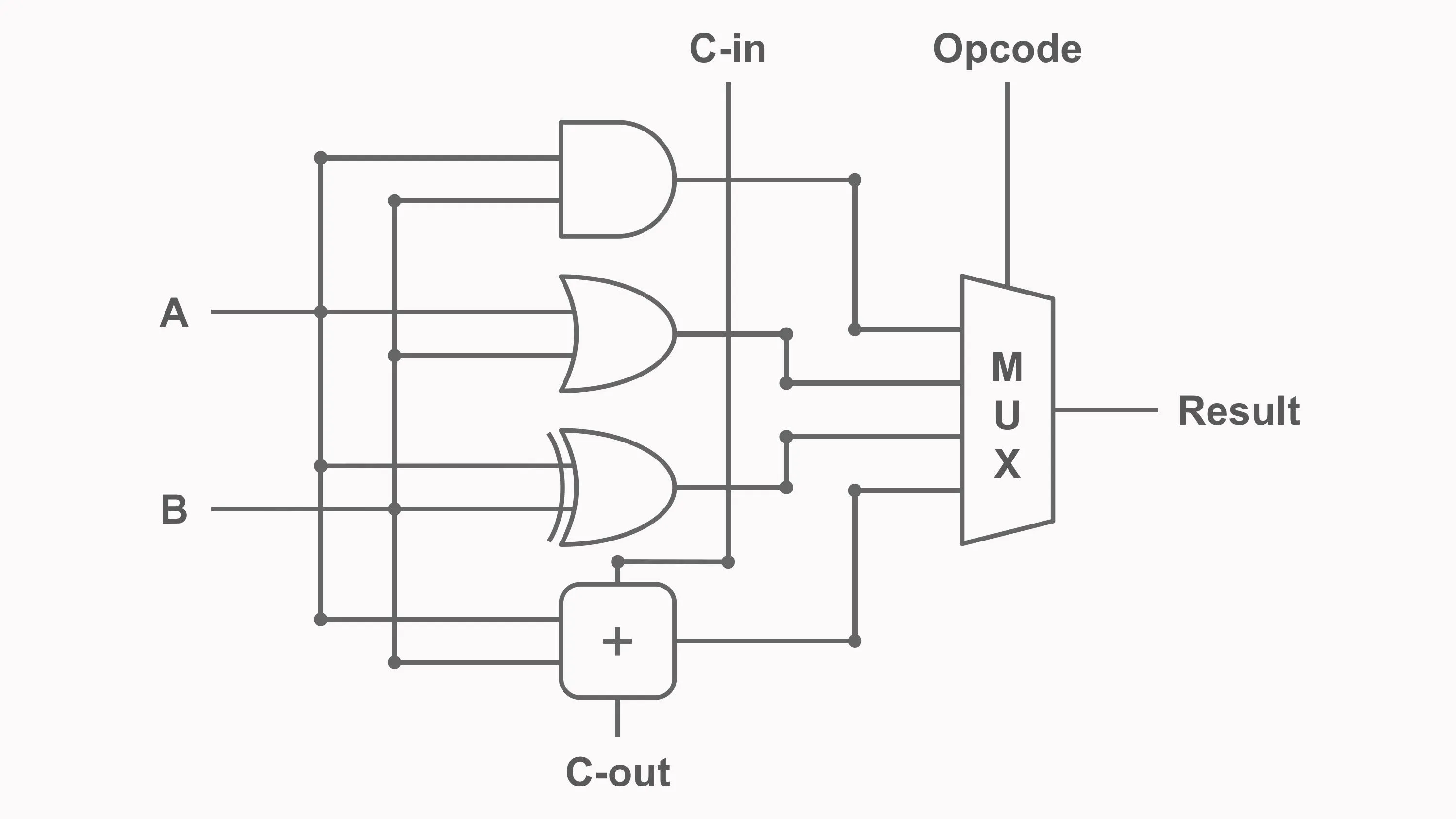
How the 1-Bit ALU Works
The sequence is:
- Inputs
A,B, andC_inarrive. - The AND circuit calculates
A AND B. - The OR circuit calculates
A OR B. - The XOR circuit calculates
A XOR B. - The full-adder calculates
A + B + C_in. - The control signal configures the multiplexer.
- The selected result becomes output
Y. - The full-adder also produces
C_outfor the next arithmetic stage.
Example behaviour:
A | B | C_in | Control | Operation | Y | C_out |
|---|---|---|---|---|---|---|
| 0 | 1 | 0 | 00 | AND | 0 | 0 |
| 0 | 1 | 0 | 01 | OR | 1 | 0 |
| 1 | 1 | 0 | 10 | XOR | 0 | 0 |
| 0 | 1 | 0 | 11 | ADD | 1 | 0 |
| 1 | 1 | 0 | 11 | ADD | 0 | 1 |
| 1 | 1 | 1 | 11 | ADD | 1 | 1 |
The final two rows show why carry-out is essential. Adding 1 + 1 produces a Sum bit of 0 and a carry-out of 1.
Expanding the 1-Bit ALU into an 8-Bit ALU
To process wider numbers, several one-bit ALU slices can be placed side by side.
For an 8-bit ALU:
- slice 0 processes
A0andB0; - slice 1 processes
A1andB1; - the pattern continues through slice 7.
All slices receive the same operation-control signal.
During logical operations, each bit is processed independently.
During addition, the carry-out of each slice becomes the carry-in of the next:
C_out[0] -> C_in[1]
C_out[1] -> C_in[2]
...
C_out[6] -> C_in[7]
This creates an 8-bit ripple-carry arithmetic path.
The same idea can be extended to 16, 32, or 64 bits, although wider and faster processors often use more advanced carry networks.
Adding Subtraction to the 1-Bit ALU
Subtraction can be added without including a separate full-subtractor in every slice.
Introduce a SUB control signal:
B_modified = B XOR SUBThe least significant slice receives:
C_in[0] = SUBWhen SUB = 0, the ALU adds:
A + BWhen SUB = 1, it calculates:
A + (NOT B) + 1which equals:
A - BEvery slice still uses a full-adder. The added XOR gates and initial carry control convert it into an adder-subtractor.
Selecting Between Arithmetic and Logic Results
A larger ALU can be understood as two layers:
- Function circuits generate candidate results.
- Selection logic chooses the required result.
For one bit, the candidates might be:
AND_result
OR_result
XOR_result
ADD_SUB_result
The multiplexer forwards one candidate to Y.
Across an 8-bit ALU, eight multiplexers use the same control value so that every bit performs the same operation.
What About Shift Operations?
A shift moves bits left or right.
For example:
00110110 << 1 = 01101100A simple left shift by one position can be implemented mostly through wiring. A variable shift by several positions requires a more capable circuit, often called a barrel shifter.
Depending on the processor, the shifter may be:
- integrated into the ALU;
- placed beside the ALU;
- implemented as a separate execution unit.
This is another example of why the exact boundaries of an ALU vary between CPU designs.
ALU Timing and Propagation Delay
An ALU is built from physical gates, and every gate requires time to respond.
The total delay depends on the longest signal path through the selected operation.
For a ripple-carry adder, the worst-case path may require a carry to travel through every bit slice. An 8-bit ALU is therefore usually slower than a single one-bit slice, and a 64-bit ripple-carry path would be slower still.
Processor designers improve arithmetic speed with techniques such as:
- carry-lookahead;
- carry-select;
- parallel-prefix addition;
- pipelining;
- speculative execution;
- multiple execution units.
The simple 1-bit slice remains useful because it reveals the logical structure without hiding it behind optimization.
Common ALU Misconceptions
The ALU Is Not the Control Unit
The ALU performs operations. The control unit interprets instructions and configures the data path.
The Instruction Opcode Is Not Always the ALU Control Code
Instruction decoding usually transforms opcode and function fields into internal control signals.
An ALU Does Not Necessarily Contain Separate Adders and Subtractors
Subtraction can reuse an adder through two’s-complement inversion and an initial carry-in of 1.
A 1-Bit Adder Output Is Not Always the Complete Arithmetic Result
For 1 + 1, the Sum bit is 0, but the carry-out is 1. Both signals are required to build a multi-bit result.
Carry and Overflow Are Not the Same
Carry describes an extra unsigned bit. Overflow describes a signed result that cannot fit in the chosen width.
Logic Operations Do Not Directly Make Decisions
The ALU produces values and flags. Branch and control circuitry interprets them according to the instruction.
Every ALU Is Not Designed the Same Way
Operation sets, control encodings, flag behaviour, shift support, and arithmetic implementations vary across processor architectures.
Frequently Asked Questions
What does an ALU do in a CPU?
An ALU performs arithmetic and bitwise logic operations on binary operands. It also commonly produces status signals such as zero, carry, negative, and overflow.
What is the difference between an ALU and a CPU?
The CPU is the complete processing system, including registers, control logic, execution units, and interfaces. The ALU is one component inside the CPU.
How does an ALU subtract binary numbers?
Many ALUs calculate A - B as A + (NOT B) + 1. This uses the two’s complement of B and allows the normal adder to perform subtraction.
Why does a 1-bit ALU need carry-in?
Carry-in allows the slice to receive a carry from the previous binary position. Without it, one-bit slices cannot correctly perform multi-bit addition.
What is the role of a multiplexer in an ALU?
A multiplexer selects one candidate operation result, such as AND, OR, XOR, or ADD, and forwards it to the ALU output.
How does an ALU compare two numbers?
One common method is to subtract one operand from the other and examine the result together with status flags. Equality, signed ordering, and unsigned ordering require different flag interpretations.
What is the zero flag?
The zero flag indicates that every bit of the ALU result is zero. It is often used by comparison and branch instructions.
What is signed overflow?
Signed overflow occurs when the true result of a signed arithmetic operation cannot be represented with the available number of bits.
Are multiplication and division part of the ALU?
They may be, but not always. Some processors use separate multiplier, divider, or floating-point units, while simpler processors may perform those operations through repeated ALU steps.
How is an 8-bit ALU built?
An 8-bit ALU can be built from eight one-bit slices. Each slice handles one bit of the operands, and arithmetic carry signals connect neighbouring slices.
Key Takeaways
An ALU combines arithmetic circuits, logic gates, selection logic, and status detection into a configurable execution unit.
The main ideas are:
- The ALU performs arithmetic and bitwise logic operations.
- The control unit decodes instructions and configures the ALU.
- A half-subtractor calculates Difference and Borrow for two bits.
- A full-subtractor includes a borrow-in value.
- Practical ALUs often subtract by calculating
A + (NOT B) + 1. - One adder can therefore support addition, subtraction, increment, and decrement.
- AND, OR, XOR, and NOT operate independently on corresponding bits.
- A multiplexer selects which candidate operation becomes the final result.
- A 1-bit arithmetic slice needs both carry-in and carry-out.
- Multiple slices form wider ALUs.
- Zero, carry, negative, and overflow flags describe important properties of the result.
- Carry and signed overflow represent different conditions.
We have now combined logic gates and adders into a configurable processing circuit. In the next chapter, we will examine the control unit, which decodes instructions and coordinates the ALU, registers, memory, and data paths throughout the CPU.