How a CPU Executes Instructions: The Fetch-Decode-Execute Cycle
Follow the fetch-decode-execute cycle step by step and learn how the program counter, registers, ALU, control unit, cache, and write-back stages execute machine code.
In the previous chapters, we built the main ideas behind a processor one layer at a time. We began with transistors, combined them into logic gates, built adders and memory circuits, assembled an Arithmetic Logic Unit, explored the Control Unit, and examined the memory hierarchy.
We can now bring those components together and follow a machine instruction through the CPU.
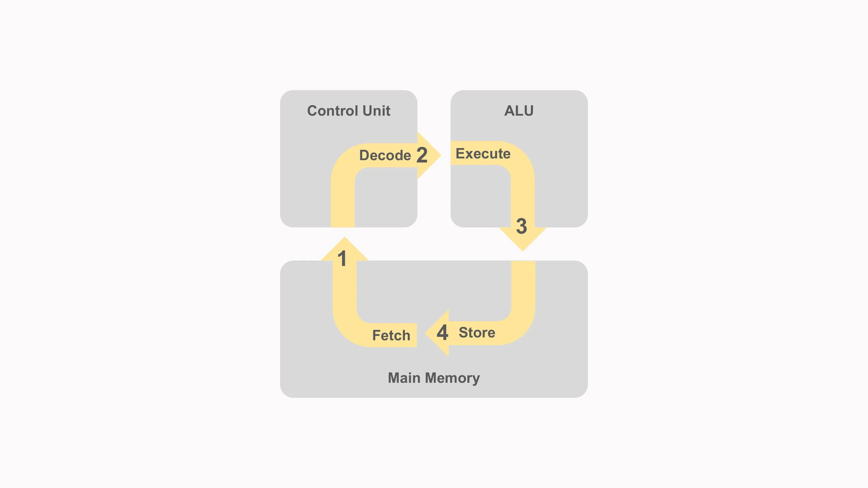
At the architectural level, instruction execution is often explained as a repeating fetch-decode-execute cycle:
- Fetch an instruction.
- Decode what it means.
- Obtain its operands.
- Execute the required operation.
- Access memory if necessary.
- Write back or commit the result.
- Continue with the next instruction.
This model explains the essential work every processor must perform. Real CPUs may overlap, split, reorder, predict, cache, and pipeline these steps, but the same logical responsibilities remain.
What You Will Learn
By the end of this chapter, you will understand:
- how the major CPU components cooperate;
- what the program counter represents;
- how instruction fetching works;
- how instruction bytes are decoded;
- how registers and immediate values supply operands;
- what happens during the execute stage;
- when a memory-access stage is required;
- what write-back and retirement mean;
- how arithmetic instructions update status flags;
- how branches change the instruction stream;
- how caches and virtual-memory translation participate in execution;
- why modern processors overlap many instructions;
- how pipelining differs from one-instruction-at-a-time execution;
- how out-of-order execution preserves correct program behaviour.
Bringing the CPU Components Together
A processor is not only an ALU connected to memory. It is a coordinated system of storage, control, execution, and communication structures.
A simplified CPU contains:
- a program counter;
- an instruction-fetch mechanism;
- an instruction decoder;
- registers;
- a Control Unit;
- an ALU;
- multiplexers and buses;
- status or condition information;
- cache and memory interfaces.
More advanced processors may also contain:
- several execution units;
- branch predictors;
- instruction and data caches;
- TLBs;
- vector units;
- floating-point units;
- load-store units;
- reorder buffers;
- register-renaming structures;
- instruction schedulers.
Each component solves part of the instruction-execution problem.
Registers
Registers are small, low-latency storage locations inside the processor.
Depending on the instruction-set architecture and implementation, registers may hold:
- arithmetic operands;
- memory addresses;
- function arguments;
- return values;
- temporary results;
- stack locations;
- status information;
- vector data.
Some educational CPU designs also use a visible Instruction Register, or IR, to hold the instruction currently being processed.
Modern pipelined processors may internally hold many fetched and decoded instructions simultaneously rather than relying on one single physical instruction register. The instruction-register concept remains useful for understanding a simple processor, but it should not be treated as a universal implementation requirement.
Program Counter
The Program Counter, or PC, represents the address associated with the next instruction in the architectural execution sequence.
Some architectures use another name, such as Instruction Pointer.
During ordinary sequential execution, the processor advances the program counter to the following instruction.
A branch, jump, call, return, interrupt, or exception can replace it with another address.
For a fixed-length instruction set, advancing may be as simple as:
PC = PC + instruction_sizeFor a variable-length instruction set, the processor must first determine the current instruction’s length.
Internally, a modern CPU may track several predicted or speculative instruction addresses at once. The architectural program counter still defines the program-visible instruction flow.
Arithmetic Logic Unit
The Arithmetic Logic Unit, or ALU, performs operations such as:
- addition;
- subtraction;
- bitwise AND;
- bitwise OR;
- bitwise XOR;
- comparisons;
- address calculations.
The ALU receives operands and an operation-selection signal.
It then produces:
- a result;
- status information such as zero, carry, negative, or overflow.
The ALU does not fetch instructions or choose its operation independently. Other processor logic routes the operands and supplies the required control signals.
Control Unit
The Control Unit coordinates instruction execution.
It uses decoded instruction information and processor state to control:
- register reads;
- register writes;
- ALU operation selection;
- immediate-value selection;
- memory reads and writes;
- program-counter updates;
- result routing;
- status-flag updates.
The Control Unit is often compared with an orchestra conductor. The analogy is useful because the Control Unit coordinates components rather than performing every operation itself.
In a modern CPU, control logic is distributed across instruction fetching, decoding, scheduling, execution, memory handling, and retirement rather than existing as one simple centralized box.
Buses and Multiplexers
A CPU must move values between registers, execution units, caches, and other structures.
Introductory diagrams often use buses to represent shared data paths.
A multiplexer chooses one value from several possible sources.
For example, the second ALU input might come from:
- a register;
- an immediate value;
- the constant
1; - the program counter;
- a forwarded result from another instruction.
The decoded instruction determines which source should be selected.
The Instruction Cycle
The instruction cycle describes the logical stages required to process a machine instruction.
A useful expanded model is:
Fetch -> Decode -> Read Operands -> Execute -> Memory -> Write-BackNot every instruction requires meaningful work in every stage.
For example:
- an ADD instruction may not access data memory;
- a STORE instruction may not write a register result;
- a branch may update the program counter instead of a general-purpose register;
- a no-operation instruction performs almost no visible work.
The stages are a framework for understanding responsibilities, not a rule that every instruction must spend exactly one clock cycle in each stage.
Stage 1: Fetch the Instruction
The CPU begins by obtaining the instruction located at the current program-counter address.
Conceptually:
instruction = Memory[PC]In a modern system, the request normally passes through several structures:
- The program counter supplies a virtual instruction address.
- The instruction TLB helps translate that virtual address.
- The instruction cache is checked.
- On a cache miss, the request continues to lower cache levels or main memory.
- The returned instruction bytes enter the processor’s fetch and decode structures.
The processor may fetch more than one instruction or several bytes at once.
Instruction Fetch and Cache Lines
Instruction caches transfer blocks rather than fetching only one byte at a time.
A cache line may contain several consecutive instructions.
This works well because programs usually execute nearby instructions sequentially, demonstrating spatial locality.
When a loop runs repeatedly, its instructions may remain in the cache, demonstrating temporal locality.
Instruction caching allows the front end to supply instructions much faster than repeatedly reading them from DRAM.
Instruction Fetch and Virtual Memory
Instruction addresses used by a process are normally virtual addresses.
The Memory Management Unit and instruction TLB participate in translating those addresses.
The page mapping must also permit instruction execution.
If the page is:
- not currently mapped;
- not resident when required;
- marked as non-executable;
- inaccessible at the current privilege level;
the processor raises an exception and the operating system determines how to respond.
Instruction fetching therefore depends on both the cache hierarchy and virtual-memory permissions.
Advancing the Program Counter
For ordinary sequential execution, the processor calculates the address following the current instruction.
In a fixed-length fictional architecture with four-byte instructions:
next_PC = PC + 4In a variable-length architecture, the increment depends on the decoded instruction length.
The sequential next address may later be replaced by:
- a branch target;
- a jump target;
- a function-return address;
- an interrupt handler;
- an exception handler.
A modern CPU may predict the next address before the current branch has finished executing.
Stage 2: Decode the Instruction
During decode, the processor interprets the instruction bits.
The decoder may determine:
- the operation;
- source registers;
- destination register;
- operand width;
- immediate values;
- addressing mode;
- whether memory is read or written;
- whether status flags change;
- whether control flow may change.
The exact fields depend on the Instruction Set Architecture.
Instruction Fields
Consider a simplified fictional instruction encoding:
Opcode | Destination | Source 1 | Source 2An ADD instruction might encode:
ADD R1, R2, R3with the architectural meaning:
R1 = R2 + R3The decoder identifies:
- operation: ADD;
- destination:
R1; - first source:
R2; - second source:
R3.
A real instruction format may be fixed length, variable length, or divided across several function and operand fields.
Opcode vs Internal Operation
The opcode identifies the architectural instruction.
The processor may translate it into internal control information.
For example:
Architectural ADD instruction
        |
        v
Decoded internal ADD operation
        |
        v
ALU control = addition
A load instruction may also use the ALU’s addition function to calculate an address:
address = base_register + offsetThe architectural operation is LOAD, while one internal execution operation is ADD.
This distinction explains why the machine-code opcode and the ALU control signal are not always the same.
Immediate Values
Some instructions contain a constant inside the instruction itself.
For example:
ADD R1, R2, #5might mean:
R1 = R2 + 5The value 5 is an immediate operand.
The decoder extracts and extends it to the required width.
Depending on the instruction, extension may be:
- zero extension;
- sign extension;
- another architecture-defined transformation.
A multiplexer then selects the immediate value instead of a second register.
Microcode and Decode
Some processor designs translate selected instructions into sequences of lower-level internal operations.
A microcoded or internally sequenced instruction may require several control steps.
Other instructions may decode directly into one or more internal operations through hardwired logic.
The details depend on the microarchitecture. The same instruction-set architecture can be implemented differently by different processor generations.
It is therefore safer to say that microcode may participate in decoding or sequencing selected instructions rather than assuming it is used for every complex-looking instruction.
Register Renaming in Modern CPUs
Architectural instructions name registers defined by the ISA.
Out-of-order processors may internally map those names to a larger set of physical registers.
This process is called register renaming.
Renaming prevents unrelated instructions from being forced to wait merely because they reuse the same architectural register name.
For example:
R1 = R2 + R3
R1 = R4 + R5
The second instruction overwrites architectural R1, but the processor can temporarily assign the two results to different physical registers.
The correct final mapping becomes visible when instructions retire in program order.
Stage 3: Read the Operands
After decoding, the processor must obtain the values required by the instruction.
For a register-register addition:
R1 = R2 + R3the source operands are:
value_in_R2
value_in_R3
A simple CPU may read both directly from the register file.
A modern processor may instead obtain an operand from:
- a physical register;
- a result-forwarding path;
- a temporary execution buffer;
- a completed earlier instruction;
- memory after a load finishes.
The instruction cannot execute until its required operands are available.
Data Dependencies
Instructions often depend on earlier results.
Consider:
R1 = R2 + R3
R4 = R1 AND R5
The second instruction needs the new value of R1.
This is a read-after-write dependency.
A simple pipeline may wait until the first instruction writes back.
A faster design may forward the result directly from the ALU output to the next execution unit without waiting for register write-back.
This technique is called forwarding or bypassing.
Stage 4: Execute the Operation
During execution, the selected hardware performs the required operation.
For an ADD instruction:
- Source operands reach the ALU.
- ALU control selects addition.
- The adder produces a result.
- Carry and overflow logic produce status information.
For a bitwise AND:
- Corresponding operand bits enter AND gates.
- The resulting bits form the output word.
For a branch:
- Comparison logic evaluates the condition.
- Address-generation logic calculates the target.
- The next instruction address is selected.
The execute stage can therefore mean different things depending on the instruction.
Arithmetic Example
Suppose:
R2 = 13
R3 = 29
and the instruction is:
ADD R1, R2, R3The ALU receives:
A = 13
B = 29
operation = ADD
It calculates:
13 + 29 = 42The binary values might be:
00001101
00011101
--------
00101010
The result 00101010 represents decimal 42.
Status Flags
An arithmetic instruction may update status flags.
Common examples include:
Zero Flag
Set when every result bit is zero.
Carry Flag
Often records carry out for unsigned addition.
Subtraction conventions vary by architecture.
Negative Flag
Commonly copies the most significant result bit.
Overflow Flag
Indicates that a signed result cannot be represented in the available width.
Not every instruction updates every flag, and some architectures avoid a general status register entirely or update conditions only through special instructions.
The ISA defines the visible behaviour.
Comparisons
A comparison may reuse subtraction logic.
To test whether two values are equal, the processor can calculate:
A - BIf the result is zero, the values are equal.
The comparison instruction may discard the arithmetic result and preserve only status information or write a Boolean result to a register.
Signed and unsigned ordering require different interpretations of carry, sign, and overflow.
Address Calculation
Load and store instructions often use the ALU or a dedicated address-generation unit.
For an instruction conceptually written as:
LOAD R1, [R2 + 16]the effective address is:
address = R2 + 16The execution hardware calculates the address before the memory system can read the requested data.
The operation is a LOAD architecturally, but the execute stage still performs addition.
Stage 5: Access Memory
Only instructions that require data memory perform a meaningful memory-access stage.
Examples include:
- loads;
- stores;
- stack operations;
- atomic memory operations;
- selected vector operations.
A load reads data from a memory address.
A store writes data to a memory address.
Load Instruction
Consider:
LOAD R1, [R2 + 16]A simplified sequence is:
- Read
R2. - Add the immediate offset
16. - Translate the virtual address.
- Check the data cache.
- Obtain the data.
- Deliver it to the destination register path.
A cache hit may satisfy the load quickly.
A miss may require lower cache levels or main memory.
A page fault may require operating-system assistance.
Store Instruction
Consider:
STORE [R2 + 16], R1A simplified sequence is:
- Read base register
R2. - Read data register
R1. - Calculate the effective address.
- Translate the virtual address.
- check permissions;
- update the cache or memory subsystem according to the cache policy.
In an out-of-order processor, a store may wait in a store buffer until it is safe to become architecturally visible.
This helps preserve precise program behaviour while allowing other work to continue.
Memory Ordering
Processors may execute memory operations internally in ways that differ from simple program order.
The architecture defines which reorderings software is allowed to observe.
Multithreaded programs use:
- atomic instructions;
- memory barriers;
- locks;
- synchronization primitives;
to coordinate shared memory correctly.
The fetch-decode-execute model describes one instruction logically, but correct multicore execution also depends on memory-ordering and coherence rules.
Stage 6: Write-Back
During write-back, a result is stored in its architectural destination.
For:
ADD R1, R2, R3the destination is R1.
Conceptually:
R1 = ALU_resultA load instruction writes the value obtained from memory.
Some instructions do not write a general-purpose register:
- STORE writes memory;
- BRANCH may change the program counter;
- COMPARE may update flags;
- a no-operation may update no visible data.
Write-back is therefore operation-dependent.
Write-Back vs Retirement
In a simple in-order CPU, writing a result and completing the instruction may happen together.
In an out-of-order CPU, these concepts are often separated.
Execution Completion
The instruction has produced its internal result.
Write-Back
The internal result becomes available to dependent operations, often by entering a physical register or forwarding network.
Retirement or Commit
The instruction’s effects become part of the official architectural state in program order.
Separating execution from retirement allows younger independent instructions to execute early while preserving the appearance of ordered program execution.
Precise Exceptions
Processors aim to provide precise exceptions.
When an exception is reported:
- older instructions appear completed;
- the faulting instruction is identified;
- younger speculative instructions appear not to have changed architectural state.
Retirement logic helps preserve this model even when instructions executed out of order internally.
If an instruction on a speculative path causes an effect that never retires, its architectural result is discarded.
Complete Walkthrough: ADD R1, R2, R3
Let us follow a simplified fictional instruction:
ADD R1, R2, R3Architectural meaning:
R1 = R2 + R3Assume:
R2 = 13
R3 = 29
Step 1: Fetch
The program counter identifies the instruction address.
The processor:
- translates the virtual instruction address;
- checks the instruction cache;
- obtains the instruction bytes;
- prepares the sequential next address.
In a simple CPU, the instruction may be copied into an instruction register.
In a pipelined CPU, it enters a fetch or decode queue.
Step 2: Decode
The decoder identifies:
Operation        = ADD
Source register 1 = R2
Source register 2 = R3
Destination       = R1
Operand type      = register
Internal control information selects:
- two register sources;
- integer addition;
- ALU result as the destination value;
- register write enable.
If the architecture defines flag updates for this instruction, the corresponding control is enabled.
Step 3: Read Operands
The register system supplies:
operand_A = 13
operand_B = 29
In an out-of-order processor, the instruction may wait until both physical source operands are ready.
Step 4: Execute
The ALU calculates:
13 + 29 = 42In binary:
  00001101
+ 00011101
----------
  00101010
Status logic determines properties of the result.
For this example:
Zero     = 0
Negative = 0
Carry and overflow depend on the chosen operand width, but neither is required for the ordinary decimal interpretation shown here.
Step 5: Memory Stage
The ADD instruction does not need data memory.
A pipeline may still contain a position named “Memory,” but the instruction simply passes through or bypasses any unused memory-access work.
Step 6: Write-Back
The result is routed to the destination:
R1 = 42A simple CPU now considers the instruction complete.
An out-of-order CPU may first write the value to a physical register and later retire the instruction, updating the architectural mapping for R1.
Step 7: Continue
Execution proceeds using the next architectural instruction address.
If no branch or exception changes control flow, that address is the sequential successor.
Meanwhile, a pipelined CPU may already have fetched, decoded, or executed several other instructions.
Walkthrough: Load from Memory
Now consider:
LOAD R1, [R2 + 16]Assume:
R2 = 0x1000The effective virtual address is:
0x1000 + 0x10 = 0x1010The CPU then:
- decodes the LOAD;
- reads
R2; - calculates virtual address
0x1010; - obtains the address translation through the TLB or page tables;
- checks memory permissions;
- checks the data cache;
- receives the value;
- writes it to
R1; - retires the instruction when safe.
If the data is not in the closest cache, the load waits for a lower cache or main memory.
If the translation requires operating-system assistance, a page fault occurs.
Walkthrough: Store to Memory
Consider:
STORE [R2 + 16], R1The processor:
- decodes the STORE;
- reads address base
R2; - reads store data from
R1; - calculates the virtual address;
- translates the address;
- checks write permissions;
- places the store into the memory system;
- retires the instruction according to ordering rules.
The data may first update a cache rather than being written immediately to DRAM.
Under a write-back cache policy, the modified cache line can remain dirty until it is evicted or otherwise written to a lower level.
Walkthrough: Conditional Branch
Consider a fictional instruction:
BEQ R1, R2, targetmeaning:
Branch to target if R1 equals R2The processor:
- fetches and decodes the branch;
- obtains
R1andR2; - compares the values;
- calculates or retrieves the target address;
- chooses between the target and sequential address.
A simple CPU may wait for the comparison before fetching the next instruction.
A faster CPU predicts the likely outcome and continues fetching speculatively.
Branch Prediction
Branches create uncertainty because the next instruction address may not be known immediately.
A branch predictor guesses:
- whether a conditional branch will be taken;
- which target address should be used.
If the prediction is correct, the pipeline remains busy.
If it is wrong:
- instructions from the incorrect path are discarded;
- the correct program counter is selected;
- fetching restarts from the correct path.
The program result remains correct, but the incorrect prediction costs time.
Pipelining
A simple processor can complete one instruction before beginning the next.
A pipelined CPU overlaps different stages of several instructions.
A five-stage teaching pipeline might be:
IF -> ID -> EX -> MEM -> WBwhere:
IF= instruction fetch;ID= instruction decode and register read;EX= execute;MEM= memory access;WB= write-back.
At one moment:
| Instruction | Current stage |
|---|---|
| Instruction 1 | Write-back |
| Instruction 2 | Memory |
| Instruction 3 | Execute |
| Instruction 4 | Decode |
| Instruction 5 | Fetch |
Pipelining improves throughput because several instructions make progress simultaneously.
It does not mean each instruction has zero latency. One instruction may still need several stages to travel from fetch to completion.
Throughput vs Latency
Latency is the time required for one instruction to produce its result.
Throughput is the rate at which instructions can complete or begin execution.
A pipeline may allow one instruction to complete each cycle after it fills, even though each instruction takes several cycles to travel through the pipeline.
This distinction is essential when discussing CPU performance.
Pipeline Hazards
Overlapping instructions creates situations called hazards.
Data Hazard
A later instruction needs a result that is not ready.
Example:
R1 = R2 + R3
R4 = R1 AND R5
Solutions may include:
- forwarding;
- stalling;
- out-of-order scheduling.
Control Hazard
A branch changes the next instruction address.
Solutions may include:
- waiting;
- branch prediction;
- speculative fetching.
Structural Hazard
Two instructions need the same hardware resource simultaneously.
Solutions may include:
- delaying one instruction;
- adding another resource;
- scheduling operations differently.
Superscalar Execution
A superscalar processor can issue or execute more than one instruction during a cycle when dependencies and resources allow it.
It may contain several:
- integer ALUs;
- load-store units;
- vector units;
- branch units;
- floating-point units.
The decoder and scheduler distribute internal operations across the available execution units.
The fetch-decode-execute cycle still applies logically, but multiple instructions may occupy each broad phase at once.
Out-of-Order Execution
An out-of-order processor allows ready instructions to execute before older instructions that are waiting.
Consider:
1. LOAD R1, [slow_memory_address]
2. ADD R2, R3, R4
3. XOR R5, R6, R7
4. ADD R8, R1, R9
Instruction 1 may wait for memory.
Instructions 2 and 3 do not depend on R1, so they can execute while the load waits.
Instruction 4 must wait because it depends on instruction 1.
The processor later retires results in program order, preserving architectural correctness.
Speculative Execution
A processor may perform work before it knows whether that work will be needed.
Examples include:
- executing instructions after a predicted branch;
- beginning a load before all older operations retire;
- calculating possible results early.
This is speculative execution.
Speculative results do not become architectural state until the processor confirms they belong to the correct execution path and can retire safely.
Incorrect speculative work is discarded.
Speculation improves performance but also increases control complexity and creates important security considerations.
The Role of the Clock
A synchronous CPU uses a clock to coordinate state changes.
Between clock edges:
- register outputs drive combinational logic;
- signals propagate through decoders, multiplexers, and execution circuits;
- the new values settle.
At an active clock edge:
- pipeline registers or state elements capture selected values;
- the next cycle begins.
The clock does not tell the CPU to “fetch once, decode once, execute once” on three universal pulses. Different designs divide work into different numbers of stages, and some operations take several cycles.
Does One Instruction Finish per Clock Cycle?
Not necessarily.
Possible cases include:
- a simple instruction completing in one cycle in a small CPU;
- an instruction taking several cycles in a multi-cycle CPU;
- a pipeline completing roughly one instruction per cycle after filling;
- a superscalar processor retiring several instructions in a cycle;
- a cache miss delaying one instruction for many cycles;
- a complex instruction being divided into several internal operations.
Clock frequency alone therefore does not determine performance.
Interrupts and Exceptions
Normal sequential execution can be interrupted by unusual events.
Exception
An exception is associated with instruction execution.
Examples include:
- page fault;
- invalid instruction;
- divide-by-zero;
- permission violation.
Interrupt
An interrupt is commonly generated by an external or asynchronous event, such as:
- device completion;
- timer event;
- inter-processor signal.
The processor preserves enough state to transfer control to a handler.
After handling the event, execution may resume according to architecture and operating-system rules.
Context Switching
An operating system can pause one thread and run another.
To do so, it preserves the first thread’s architectural state, which may include:
- general-purpose registers;
- program counter;
- stack pointer;
- status information;
- vector state;
- memory-management context.
It then restores the state of another thread.
The CPU continues the fetch-decode-execute process using the newly restored program state.
Machine Code, Assembly, and High-Level Languages
A CPU executes machine instructions, not source-code statements directly.
A typical software path is:
High-level source code
        |
        v
Compiler
        |
        v
Assembly or intermediate machine representation
        |
        v
Assembler and linker
        |
        v
Executable machine code
        |
        v
CPU instruction execution
A high-level expression such as:
result = a + b;may become one or more machine instructions depending on:
- optimization;
- register availability;
- data type;
- target architecture;
- surrounding code.
The CPU then processes those instructions through its execution machinery.
The CPU Does Not Literally Think
A processor can perform extremely complex tasks, but its operation is mechanical.
It:
- stores binary state;
- transforms values through circuits;
- follows instruction encodings;
- selects paths through control logic;
- responds to inputs and events.
Human descriptions such as “the CPU decides” or “the CPU thinks” are convenient shorthand.
The hardware follows physical rules and predefined logic. General-purpose behaviour emerges because software can arrange simple operations into extremely large and flexible sequences.
Common Instruction-Cycle Misconceptions
Every CPU Has One Physical Instruction Register
Simple CPUs may have one explicit instruction register. Modern processors can hold many fetched, decoded, and in-flight instructions simultaneously.
The PC Always Points to the Instruction Currently Executing
The architectural definition varies, and pipelined CPUs track several instruction addresses internally. The PC is best understood according to the ISA’s visible rules.
Fetch Always Reads Directly from RAM
Instruction fetch normally checks caches and translation structures before reaching main memory.
Every Instruction Uses Every Stage
An ADD does not need a data-memory read. A STORE may not write a register. A branch primarily changes control flow.
Execute Means Only Using the ALU
Execution can involve address generation, comparisons, shifts, vector units, branches, floating-point units, or other hardware.
Write-Back and Retirement Are Always the Same
They may coincide in a simple CPU. Out-of-order processors can produce an internal result before the instruction retires architecturally.
One Instruction Completes Before the Next Begins
Pipelined and superscalar CPUs overlap many instructions.
One Clock Cycle Equals One Instruction
Instruction latency, throughput, pipeline structure, and memory delays make this assumption unreliable.
The CPU Executes High-Level Source Code Directly
Compilers, assemblers, linkers, loaders, and operating systems transform and prepare code before the CPU executes machine instructions.
Frequently Asked Questions
What is the fetch-decode-execute cycle?
It is a model describing how a CPU obtains an instruction, interprets it, performs the requested operation, and records its result.
What happens during the fetch stage?
The processor uses an instruction address to obtain instruction bytes, normally through address translation and the instruction-cache hierarchy.
What happens during the decode stage?
The decoder identifies the operation, operands, instruction length, immediate values, destination, and required internal resources.
What happens during the execute stage?
Execution hardware performs arithmetic, logic, comparison, address generation, branch resolution, shifting, or another required operation.
What is the write-back stage?
Write-back places an instruction result into its destination path, such as a register. In an out-of-order CPU, architectural retirement may happen later.
What is the difference between the program counter and instruction register?
The program counter represents an instruction address. An instruction register, when present, stores instruction bits being processed in a simple CPU design.
Does every CPU have an instruction register?
No. It is common in teaching models and simple processors, but modern CPUs may use queues, pipeline registers, and decoded-operation buffers instead of one single instruction register.
Does every instruction access memory?
Every instruction must be fetched, but not every instruction performs a separate data-memory load or store.
Why does a CPU need cache?
Cache keeps recently or nearby used instructions and data close to the execution cores, reducing the cost of accessing main memory.
What is pipelining?
Pipelining divides instruction processing into stages and overlaps several instructions so that different stages work simultaneously.
What is out-of-order execution?
It allows ready instructions to execute before older stalled instructions, while retirement logic preserves the correct architectural result.
What is register renaming?
Register renaming maps architectural register names to a larger set of physical registers, removing false dependencies between instructions.
What happens when a branch prediction is wrong?
The CPU discards speculative work from the incorrect path and restarts fetching from the correct instruction address.
How many instructions can a CPU execute per cycle?
It depends on the processor, workload, dependencies, execution resources, cache behaviour, and instruction mix. Some CPUs can process several instructions per cycle under favourable conditions.
Does a higher clock speed always mean a faster CPU?
No. Performance also depends on work per cycle, cache behaviour, branch prediction, execution width, memory latency, and many other design factors.
Key Takeaways
The fetch-decode-execute cycle brings all major processor components together.
The central ideas are:
- The program counter identifies the architectural instruction stream.
- Fetch obtains instruction bytes through translation and the cache hierarchy.
- Decode identifies the operation, operands, destination, and required resources.
- Registers and immediate fields supply input values.
- Execution may involve an ALU, shifter, branch unit, address generator, or another execution unit.
- Load and store instructions use the virtual-memory and cache systems.
- Write-back records a result, while retirement makes it architecturally official in an out-of-order CPU.
- Status flags describe properties such as zero, carry, negative, and overflow.
- Branches can replace the sequential next program-counter value.
- Pipelining overlaps stages from multiple instructions.
- Superscalar processors can process several instructions or internal operations in parallel.
- Out-of-order execution allows independent work to continue while older instructions wait.
- Register renaming removes false dependencies.
- Speculative execution performs work before its necessity is confirmed.
- Retirement preserves the appearance of ordered execution.
- The CPU follows machine-code rules mechanically rather than literally thinking.
We began this series with a single transistor and followed the layers upward:
Transistors
    -> Logic gates
    -> Adders and memory circuits
    -> Arithmetic Logic Unit
    -> Control Unit
    -> Memory hierarchy
    -> Complete instruction execution
Each layer hides some of the complexity below it while providing more powerful building blocks above it.
A modern processor is vastly more complicated than the simplified CPU described in this series, but the essential principles remain the same: binary state is stored, moved, transformed, and coordinated through digital circuits. Software becomes useful computation because the processor repeats those operations with extraordinary speed and precision.